Beyond Purdue No. 062 / Data diodes, Networks
Fibre Optic Connector Types
Every optical port on a data diode link is specified by two independent choices: the connector family, which is the mechanical shape of the plug, and the polish, which is the geometry ground onto...
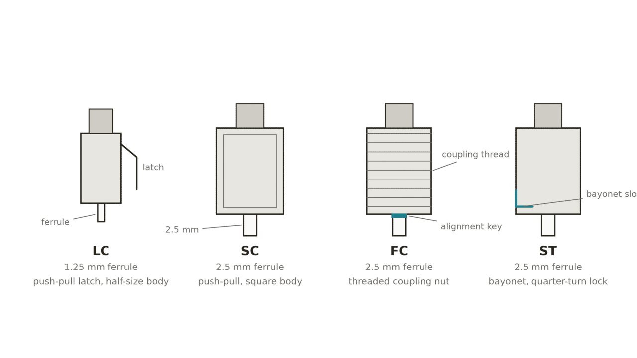
Every optical port on a data diode link is specified by two independent choices: the connector family, which is the mechanical shape of the plug, and the polish, which is the geometry ground onto the fibre endface. The product selector lists them as one combined code — LC/UPC, SC/APC, FC/UPC and so on. This note explains what each half of the code means, which combination to order, and the one mistake that damages hardware.
How to read a connector code
A designation such as SC/APC is always two parts:
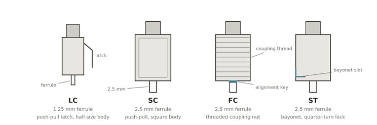
SC — the connector family. It defines the plug body, the ferrule diameter and how the connector locks into the adapter. It is purely mechanical.
APC — the polish. It defines the shape of the ceramic ferrule endface where the two fibres physically touch inside the adapter. It is purely optical.
The two are independent. Any of the four common families can be supplied with either polish, which is why the selector offers eight combinations plus None. Polish is applied to the ferrule endface, and the same connector housing is used for both UPC and APC versions.
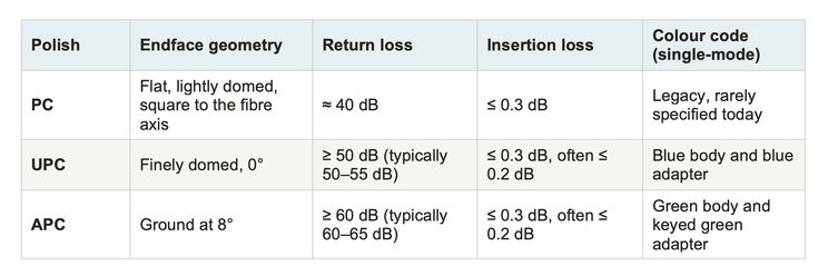
The polish: PC, UPC and APC
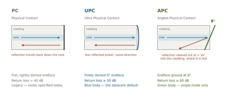
Two fibres are pressed together under spring load inside the adapter. Whatever light is not transmitted across that joint is reflected. The polish does not change how much light reflects so much as where the reflection goes, and that is what return loss measures.
What the 8° angle APC polish actually does
On a UPC joint the reflected light leaves the endface along the same axis it arrived on and travels straight back down the core toward the transmitter. On an APC joint the 8° face steers the reflection out at roughly twice the polish angle — about 16° — so it leaves the guided mode, enters the cladding and is lost. Moving from 50 dB to 60 dB is a tenfold reduction in reflected power reaching the laser.
Passive Data Diode - No Electronics, No Software, No Configuration ... possible? Write me a message.